Overview
If the kiosk you are working with has an old-style IDTech card reader, you will need to follow these steps to replace it. You will be able to tell if you have the older style if it is a black card reader that is inset on the kiosk.
Parts and Tools
To complete this task, you will need:
- a Cordless Drill
- 1 – 3/16” Drill Bit
- Screwdriver
- 4 – M4x 8mm Philips Head
- 5/16” Socket
- 4 – 6-32 Pan-head Screws
- 1 – OTI Credit Card Reader (USB)
- 4 – 6-32 K-nuts
- 1 – G3 OTI Adapter Plate
Replacing the OTI Reader
Our video teaches you how to remove and replace the OTI reader for service on a Gen3 and Gen3c MicroMarket.
You may also follow along with the steps below.
Open the Kiosk
- Insert a pencil or pen into the hole on the right side of your kiosk. The Power button is inset about three inches inside that hole. Press the button and release it, then wait for the Windows Shutdown Process to complete.
NOTE: Always shut the kiosk down using the Power button. Never unplug it to shut it off! - Remove the two screws from the back of the top bezel of the kiosk.
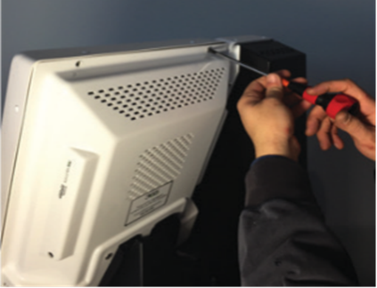
- Carefully open the kiosk. We recommend that you support the front of the kiosk in service position with a “Roller Stand”, which can be purchased from your local home improvement store.

Install the OTI Reader
- Disconnect the connector on the back of the credit card reader and unplug the USB from the PC.
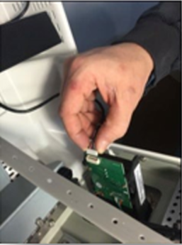
- Carefully remove the cable from the kiosk.
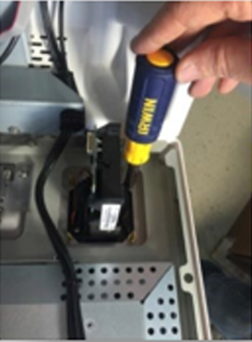
- Remove the four nuts from the CC reader and pull the CC reader from the front of the kiosk.
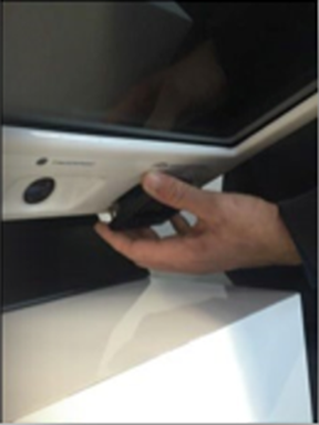
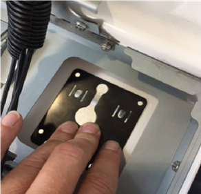
- Install the OTI adapter plate on the inside of the kiosk by aligning the four holes on the corners.5. It is very important that this orientation is correct. The slot opening must be oriented off-center and to the left (see photo below).
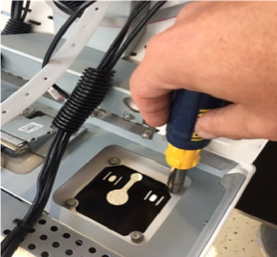
- Secure the adapter plate with the four Pan-head screws with the nuts on the inside of the kiosk.
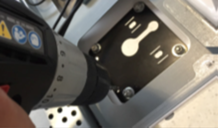
- Drill two - 3/16” holes (drill-bit included) by using the adapter plate as a template guide.
- Clean up any plastic shavings from the drilling process.
- Install the OTI Reader by feeding the USB cable through the slot of the adapter plate and aligning the four screw holes with the plate.
- Use the four M4x 8mm screws to secure the OTI device on the kiosk. Be sure it is mounted in the correct orientation.
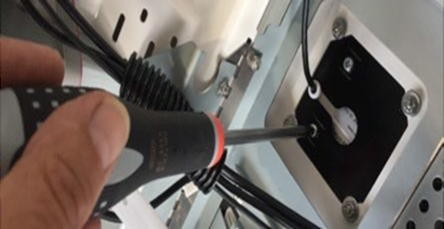
- Route the USB cable behind the sound bar up to the PC and connect it to the open USB port.
- Route the cable into the existing split loom cable protector, coil the excess cable, and secure it with zip ties as shown.
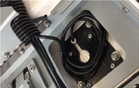
- Make sure the cable is properly routed and protected from pinching when the kiosk is closed.
Close the Kiosk
- Carefully close the front of the kiosk and make sure no cables get pinched.

- Align the kiosk front bezel with the screw holes and replace the two 10-24 Philips head screws.
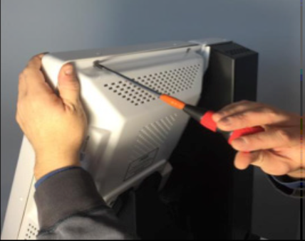
- The screws must be aligned perpendicular to the front surface of the kiosk.